
Mantaray Pro Wireless DIY Edition Build Guide
Share
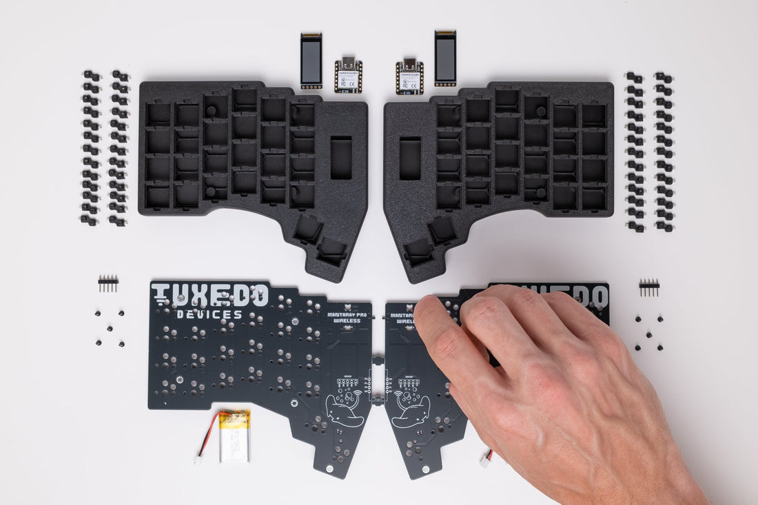
Welcome, and congratulations on starting your Mantaray Pro Wireless build! This guide will walk you through every step of the assembly process. Building a keyboard is a uniquely rewarding experience, and we're here to make it as smooth and enjoyable as possible.
Estimated Build Time: 1-3 hours Difficulty: Intermediate
Before You Begin:
We know you're excited to get started, but please read this guide in its entirety before touching any components. Some steps require specific procedures and careful attention to detail. Understanding the full process beforehand will save you time and prevent potential mistakes. Trust us on this one!
Part I: Preparation
1. Gather Your Tools
A good build starts with the right tools. Here’s what you’ll need to have on hand:
Required:
- Soldering Iron (a temperature-controlled model is highly recommended)
- Solder (low-temp, leaded solder like 63/37 is recommended for ease of use)
- Flush Cut Pliers / Snips
- Kapton Tape (or other heat-resistant tape)
- Tweezers
Recommended:
- Solder Wick or a Solder Sucker (for fixing mistakes)
- Multimeter (to check for continuity as you go)
- A well-lit workspace
Part II: PCB Assembly
2. Soldering the Microcontrollers (XIAO nRF52840 Plus)
This is the most critical step. The microcontrollers are the brains of your keyboard. Take your time, work carefully, and you'll do great.
⚠️ Important Cautions:
- Alignment is key. The microcontroller uses castellated pads, so it must be perfectly centered on the PCB pads.
- Use low heat. A low-temperature solder and a conservative iron temperature will prevent damage to the sensitive components.
- BE CAREFUL around the small black power switch on the PCB. Applying heat near it or touching it with your iron can damage it permanently.
Procedure:
- Identify Left & Right: Your kit includes a Left (L) and Right (R) PCB, and a corresponding Left (L) and Right (R) microcontroller. The firmware is side-specific, so it's crucial to match them correctly.
- Position the Left Controller: Place the left PCB on your work surface with the bottom side facing up (the side with the QR code). Place the left microcontroller onto its silkscreen outline.
- Align Perfectly: Look closely at the castellated pads on the edge of the microcontroller. Align them so they are perfectly centered over the gold pads on the PCB. You should see an equal amount of the PCB pad on either side of each microcontroller pad.
- Tape it Down: Once aligned, use a small piece of Kapton tape to hold the microcontroller firmly in place. This prevents it from shifting while you work.
- Tack Solder: Solder just one pad on one side of the microcontroller. Then, check the alignment again. If it's shifted, simply re-melt that single solder joint and nudge the controller back into position.
- Secure the Other Side: Once you're happy with the alignment, solder one pad on the opposite side to lock it in place. You can now carefully remove the tape.
- Finish Bottom Soldering: Carefully solder the remaining castellated pads. Your goal is a strong, clean connection for each pad. Ensure no solder has "bridged" or accidentally connected two pads together.
- Solder Top Battery Pads: Flip the board over to the top side. You will see cutouts where the microcontroller sits underneath. Carefully solder the battery pads on the microcontroller through these cutouts to the plated holes on the PCB. Ensure the positive (+) and negative (-) pads have a secure connection.
- Repeat for the Right Side: Follow the exact same procedure (steps 2-8) for the right PCB and right microcontroller.
Give yourself a pat on the back. You just completed a precision soldering job!
3. Installing the Hotswap Sockets
Now for something a bit more relaxing. We'll install the sockets that allow you to change your switches anytime you want.
- Orientation is Important: Look at a hotswap socket. One side is square, while the other is chamfered. The white silkscreen outline on the PCB matches this shape.
- Place and Solder: Place a hotswap socket onto the PCB, matching its shape to the silkscreen outline. Solder both metal tabs to the PCB pads, ensuring the solder flows nicely to create a secure connection.
- Repeat: Continue this process for all 26 sockets on the left PCB, and all 26 sockets on the right PCB.
4. Installing the nice!view Displays
This step requires precision, but we'll break it down. The goal is to mount the display perfectly flush and vertical.
⚠️ Critical Note: The display pins must not protrude from the bottom of the PCB. The battery will sit directly underneath, and any protruding pins could puncture the battery, or cause a dangerous short circuit.
Procedure (Start with the Left PCB):
- Tape the Bottom: Firmly press a piece of Kapton tape over the 5 display pin holes on the bottom of the PCB. This acts as a stopper for the pins.
- Prepare the Header Pins: Grab one of the 5-pin headers. Using pliers or tweezers, push the black plastic spacer all the way to the top of the pins. When you hold the end of the pins vertically on a table, all 5 pins should touch the surface evenly. This ensures they are all the same length. If they aren’t adjust them and make it so.
- Insert the Pins: From the top side of the PCB, insert the 5 pins into the display holes. The tape on the bottom will stop them from going through too far.
- Tack & Align: Solder just one of the outer pins. Use a minimal amount of solder. Now, check that the row of pins is perfectly vertical and not leaning. If it is, reheat the joint and adjust.
- Check the Bottom: Flip the PCB over. Confirm that no metal pin is poking through the tape. If one is, you must reheat the joints and reseat the pins until they are all flush.
- Solder the Top: Once confirmed flush, solder the remaining 4 pins from the top. Again, use just enough solder to form a good joint. Too much solder will prevent the display from sitting flat.
- Solder the Bottom (Optional but Recommended): Remove the tape from the bottom. To ensure the best connection, apply a tiny amount of solder to each pin-pad joint on the bottom. The goal is a flat, smooth joint with no sharp points.
- Remove the Spacer: The black plastic spacer is no longer needed. Use tweezers or small pliers to gently wiggle it off the pins.
- Trim the Pins: Place the nice!view display onto the pins. Mark where the top of the display's PCB meets the pins. Remove the display and use your flush cutters to trim the pins at your mark. The pins must not extend past the top of the display.
- Final Mount & Solder: Place the display back onto the trimmed pins. Ensure it sits flat and is aligned parallel to the top and side edges of the PCB. Now, carefully solder each of the 5 pins to the display.
- ⚠️ Heat Warning: Solder one pin at a time and allow the display to cool for a few seconds between each pin to avoid heat damage to the display.
- Repeat for the Right Side: Follow the same detailed procedure for the right PCB.
Whew, the hard parts are officially over. You’re on the home stretch now!
Part III: Case Assembly
5. Installing the Heat-Set Inserts
These brass inserts provide durable mounting points for your PCB and future accessories.
- Set Your Iron: Set your soldering iron to 410°F / 210°C. Make sure the tip is clean.
- Position the Insert: Use tweezers to place an insert onto the tip of your iron. The tapered end should be facing away from the iron.
- Press it in: Align the insert with one of the mounting holes in the 3D printed case. Gently and vertically press the iron down. The heat will melt the plastic, allowing the insert to sink into place.
- Hold and Remove: Once the insert is flush with the surface, use your tweezers to hold it in place and pull your soldering iron straight out. This prevents the insert from coming out with the iron.
- Repeat: Install all inserts:
-
- 5 inserts on the inside of each bottom case half (for the PCB).
- 4 inserts on the very bottom of each case half (for tenting accessories and mounts).
6. Testing Time!
It's time for a quick check to make sure everything is working before final assembly.
- Plug a USB-C cable into your computer and the other end into the XIAO microcontroller on the left PCB. The display should power on and show an image.
- Unplug the left side and test the right side in the same way.
If the displays light up, you're golden! If not, don't panic. Carefully re-check all your solder joints, especially for the microcontroller and display.
7. Battery Installation
🚨 DANGER: READ THIS SECTION 3 TIMES 🚨
LiPo batteries can be dangerous and must be handled with the utmost care. The polarity (+ and -) of battery connectors are NOT STANDARDIZED. Connecting a battery with reversed polarity can destroy your keyboard, cause a fire, and lead to serious injury or worse. YOU ARE RESPONSIBLE FOR VERIFYING POLARITY.
Procedure:
- SWITCH OFF: Ensure the power switch on the PCB is in the OFF position (pushed down, away from the USB port).
-
VERIFY POLARITY: Look at the battery connector on your PCB. It is marked with a
+. Now look at the wires coming from your battery's JST connector. The RED wire (+) MUST align with the+mark on the PCB. -
IF POLARITY IS WRONG: You must fix it before plugging it in.
- Option 1 (Preferred): Use tweezers to carefully lift the plastic tabs on the JST connector and pull out the metal crimps. Re-insert them in the correct orientation. Work on one wire at a time. NEVER let the exposed positive and negative wires touch.
- Option 2: Carefully cut, swap, and re-solder the wires. Insulate each connection thoroughly with heat shrink. NEVER let the exposed positive and negative wires touch.
- Connect and Test: Once you have triple-checked the polarity, plug the battery into the PCB. Flip the power switch to the ON position. The display should turn on.
- SWITCH OFF AGAIN: Turn the power switch back to the OFF position for final assembly.
- Repeat for the right side.
8. Final Assembly
- Place the Battery: Take the left bottom case and place the battery into the dedicated battery slot. The wires should route through the small cutout.
- Install Battery Cover: Place the plastic battery protection cover over the battery and press it firmly into place until it is fully seated. It has a cutout that matches the orientation of the battery slot.
- Insert the PCB: Insert the PCB into the case at an angle, seating the power switch side first. This is necessary to clear the switch housing.
- Secure the PCB: Align the PCB mounting holes with the heat-set inserts. Secure the PCB using the five M2 screws. Do not overtighten.
- Repeat for the right side.
Part IV: Finishing Touches
9. Attach the Top Case
Take the top case/plate for each side and carefully align it over the bottom case. It's a tight snap-fit, so work your way around the edges, gently pressing down until it's fully seated.
10. Apply Rubber Feet
Flip the keyboard over. Apply four of the adhesive non-slip rubber feet to the designated spots on the bottom of each half.
11. Install Switches
Gently press your Kailh Choc V1 switches through the top plate and into the hotswap sockets. Before installing each switch, check to ensure its two pins are straight. If they're bent, gently straighten them before pressing the switch in.
12. Install Keycaps
Press your keycaps firmly onto the switch stems. This is the final step! Satisfying, isn't it?
You're Done!
Congratulations! You've successfully built your Mantaray Pro Wireless keyboard. Take a moment to admire your work. We hope you love the feel of a keyboard built with your own two hands.
Next Steps: To learn how to use you new keyboard, connect to your devices via Bluetooth, and customize your layout, please refer to the Mantaray Pro Wireless User Manual.
Happy typing!